Add to Cart
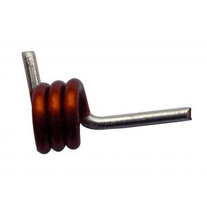
High Q Formed Shaped Heteromorphic Red Copper Air Core Coil Fixed Inductors 3 Turns 300C For for VHF-UHF RF Application
Features
Computer Optomized Coil
Utilizing Wheeler Formula
4 Wire Ties and Varnish Encapsulation
Linear A.C. Resistance
Constant Inductance with
Voltage and Current Variation
Very Low Microphonic Distortion
No Saturation Distortion
No Hysteresis Distortion
General
Inductance coil was conducted by using the principle of electromagnetic induction device.When a current flows through a wire, will produce certain electromagnetic field around that wire, and the electromagnetic field of the wire itself will be in within the scope of the electromagnetic field in the conductor induction effect.To generate electromagnetic wire itself, is called a "feeling", i.e., the change of wire itself the changes in the current magnetic field, the magnetic field and further influenced the current in the conductor;On the role of electromagnetic field in the range of other wires produce, called "mutual inductance.
Specification
| Technical Data | All technical data related to an ambient temperature of +25˚C |
| Inductance Range | 5.5nH to 27.3nH |
| Inductance Tolerance | 2%, 5%, 10% |
| Rated Current | 2.7A, 2.9A, 4.4A |
| Operating Temperature | -40˚C to +125˚C |
| Termination | 96.5% Tin/3% Silver over 0.5% Copper |
Tolerance: ± 1% centered on nominal value
Electrical Conductivity 101.5%
Temperature Range: -25°C to 85°C
Insulation Temperature: 155°C
87% Winding Space Factor
Very Low D.C.R.
Low Skin Effect Losses
Low A.C. Resistance
Low Self Capacitance
99.99% High Purity Copper

Shaped Heteromorphic coil specification parameters: 1.0mm pure copper wire, high temperature resistance, copper wire grade is 200 degrees, temperature test 300 degrees, 1 minute does not blow skin. Hollow inner diameter 3.0mm; number of turns: 3 turns. Pin stripping tin plating. Can be welded directly
Winding the coil.
The coil must be first wounded on a plastic former of the adequate diameter (equal to the required core diameter).
The winding must be tight and adjacent turns must be as close as possible.
After the winding is complete, slowly withdraw the core without disturbing the coil.
Now apply a thin layer of epoxy over the coil surface for mechanical support.
Remove the insulation from the coil ends.
Example
Suppose you want to make an inductor which produces an inductance of 10 μH. The diameter of the coil is 1 inch and the coil length is given by 1.25 inches. You will have to find the number of turns of the coil.
Thus substituting the values in the above equation
L = 10 inches
d = 1inch
l = 1.25 inches
n = √{L [18d * 40l]} / d = 26
Thus, the number of turns of the coil will be 26.
Number of turns/inch = 20.8


